

Putting a custom EPROM on an Atari 800 cartridge
Another retro computer I've been messing with is an Atari 800. It has been neglected for a long time and looks like it was left in some areas with some moisture. For the most part it works, but it has no color output. I got the Atari 800 field service manual and it talks about a SALT II diagnostic cartridge. Now that I have working EPROM burner, figured I could make one.
There's an existing design for a PCB that would accept a 2764 or 27128 but none for sale. I could probably etch my own but don't want to mess with chemicals. I have a CNC but have never tried making a PCB before and it seemed like it would be a lot of trial & error to figure out. Instead I bought the cheapest Atari 800 cartridge I could find on eBay expecting I could pop it open and use the PCB with my own ROMs.
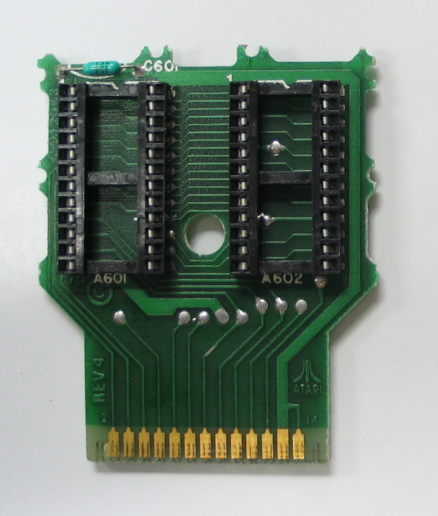 Inside was a PCB labeled as C012963 with two 24 pin sockets designed to take two 4k ROMs. I burned a couple of 2732s and slapped them on there and no-go. Thought maybe it was just because it wanted a 2532 pinout, so I convinced myself I had bought the cartridge intending to use it as a blank PCB and started cutting traces and adding jumpers. Still no go.
Checked the wiring of the PCB and found both sockets were wired in parallel! Thanks to many many people on Twitter they explained that since the ROMs were custom were made to interpret the signals differently.
I had a choice of either hacking in something like a 7400 to handle switching the signals between the 2732s, or modify the PCB to take a 2764. I decided a 2764 would be better since they are far easier to burn than the 2732s.
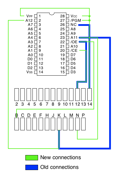
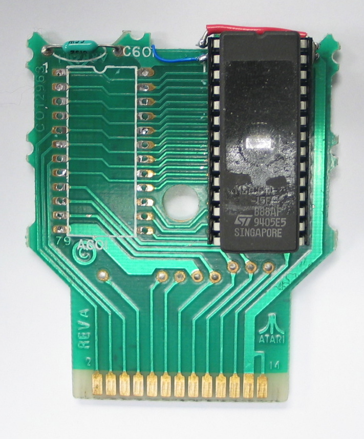 Fortunately when Intel designed the 2764 they made it nearly pin compatible with the 2732. Instead of adding 4 more pins at the bottom, they added them at the top and only moved VCC and VPP. That meant I could pretty much pull off the 24 pin socket, slap on a 28 pin socket, and just add a few jumpers to do the 2532 remapping and connect to the extra pins.
It turned out to be a pretty simple mod and surprisingly it actually worked on the first try! I only needed to cut 3 traces and add 5 jumpers along with sticking on a 28 pin socket. If you wanted to it could probably be done by piggybacking a couple of 28 pin sockets and doing the jumpering between them with no need to cut traces on the PCB.
Unfortunately burning the self test cartridge only told me what I already knew, the color on the Atari 800 doesn't work. Still no closer to figuring out specifically what component has gone bad.


+1 Posted by Eric • Mar.23.2013 at 01.21 • Reply
Do you have an oscilloscope to look at the video output waveform? It's probably either the chroma subcarrier or a cap in the circuit that combines luma and chroma.
+1 Posted by Barracuda • Mar.25.2013 at 02.05 • Reply
If you had gotten lucky enough to find a very elusive 2564 EPROM your work would have been even easier... More or less the same pinout as the 2532, and the ROMs that were on the cartridge.
+1 Posted by Paul • Apr.05.2013 at 20.56 • Reply
I did something similar to make a C64 diagnostic cartridge. The pin layout for the existing 23xx series was very similar to the 27xx series EPROM. http://biosrhythm.com/?p=973