

Put a scrolling LED display in your computer for less than $20
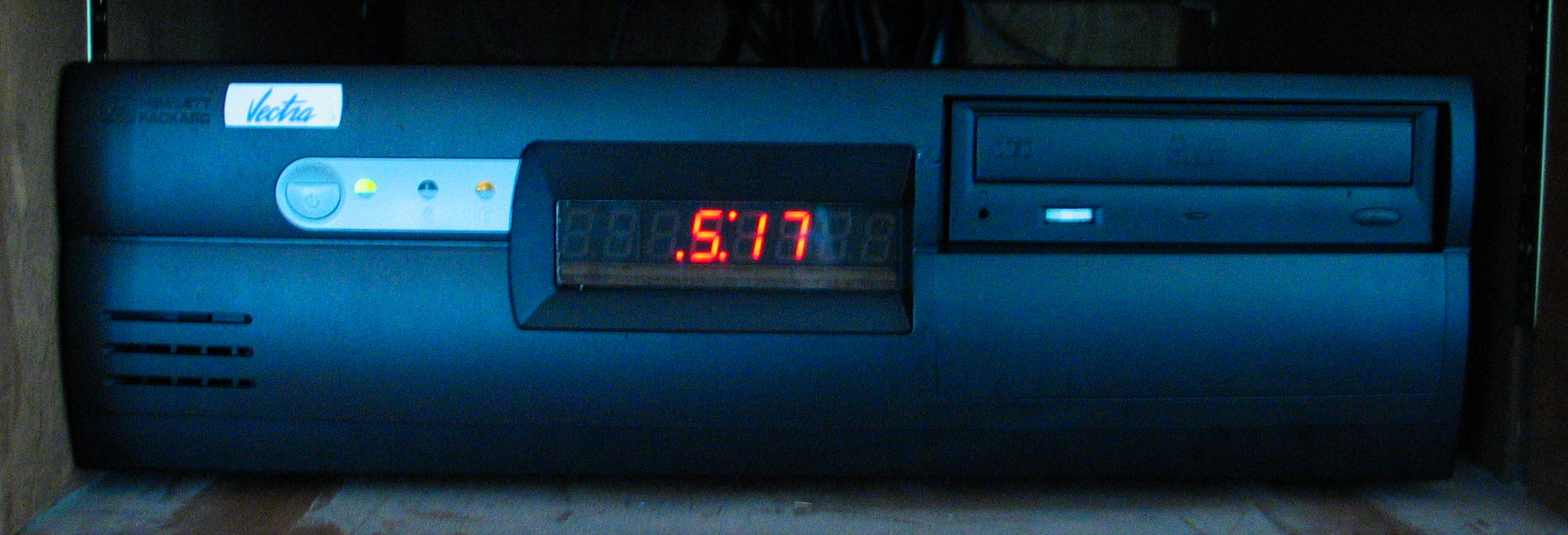
This is sort of an expansion & howto on my previous post of scroll a message on my cable box. I finally got around to building a new 8 digit display and mounting the whole thing in place of my floppy drive.
The total cost for this project was less than $20. The most expensive parts were the 7 segment displays and the ICM7218 chip. I used 0.56" tall digits. It took 4 of the LED packages to get 8 characters. The width of all of them together was exactly the same as a floppy!
First off, here's the schematic. Don't let it scare you, it's really not as complicated as it appears. Essentially you tie all the A segments together, the B segments together, etc. The only gotcha is one segment is upside down (in order to make a colon for a clock) and it is wired slightly different than the other 3.
The LED segments I used are LTD5321AR red 2-digit packages. I would have preferred to get green, but the local electronics store didn't have any other color. To hook them all together I used a donut-style perfboard and wired "traces" across it.

What a pain in the ass that was! Each color represents a single segment, and all the wires are on the front except for the gray ones which I had to jumper on the back too. Why, why, why, in this day and age can't there be an easy&cheap way to make a PCB? I have no desire to mess around with chemical etching. I don't have a CNC available to me to do milling. And I don't want to spend $40 to make a one-off proto board that I might have laid out wrong. It sure seems like there should be some way to print out a PCB from a printer.
If your 7-digit displays are Common Anode, then you want to get the ICM7218A chip. For Common Cathode, get the ICM7218B. Mine were Common Anode so I used the ICM7218A and that's the way the schematic is drawn.

For power I hooked into the 3.5" floppy power. If you happen to have a computer that has the parallel connector hooked to the motherboard from a ribbon cable, then you can wire it in to that. My computer didn't have that, so I had to put on a DB25 connector and fish a cable out the back of the computer.
After you get everything soldered up, you should test it and make sure it's working. You don't want to have to tear everything apart to go back and fix a solder joint.

Now that it's working, the next thing to do is make a base for it. Since I have lots of wood scraps and woodworking tools on-hand, I chose to make it out of wood.

Easiest way to set the width is to grab a floppy drive and stick it between the blade and the fence (WITH THE SAW TURNED OFF) and then lock the fence down. I ripped a piece of 3/8" plywood for my base.
After I cut the plywood to size I needed to make a rabbet as a sort of shelf for the LEDs to sit on. I used a router table since it's easier to setup and adjust the height on.

Don't make the shelf too thin or else it'll snap right off when you go to cut the groove. The groove is so the PCB behind the segments has something to sit in and let the segments rest flat on the board. I simply put the segments against the fence and shifted it over until it looked lined up.

To adjust the height of the blade I put the rabbet over the blade and adjusted it up until it touched the board, then made it just a little higher.

I used a hot glue gun (got it at the dollar store!) to stick the display and the brown plexi in place. The plexi came from one of those stackable file inbox thingies.

The next thing to do is pull out your floppy drive and insert your new display. Be careful while inserting it into the bracket, it's easy to snag the wires or put too much pressure on the display and snap it off the board.

After I inserted it into the bracket, I put the bracket back and slid the display up so it was flush with the front. I then forced in screws with just a screwdriver, no need to pre-drill. My case was a little tight inside so I had to use a stubby screwdriver, but the screws went in really easy into the side of the plywood.

Here is the program for Linux that drives the display.
To compile it do gcc -o icm7218 icm7218.c
I created my own custom "font" so that I can display both numbers and letters. Some of the letters may be a little strange, but every character is unique so that it's possible to get used to the font and learn to read it fluently. Uppercase and lowercase are the same, and not all symbols have been defined.
Usage is quite simple. If you call it with no arguments it will display the time. You can add it to cron and have it called every minute and it will make a nice clock.
If you want to display a message then the first argument is the message. If the message is longer than 8 characters, then you need to provide a second argument which is the number of times to scroll the message. If you need to put spaces in your message, be sure to put quotes around it. icm7218 'The quick red fox jumps over the lazy brown dog' 2
Now all I need to do is paint my case black!
Update 2006/05/01: Painted the case black yesterday. Those Vectra cases look very sharp in black.
+1 Posted by Living in the Whine Country • May.13.2006 at 18.57 • Reply
Cool walk through how to create a LED Display for your PC for less than $20, includes directions, wiring diagrams (full and simplified) and sample code for running it. I like the simplicity, it'll be easy to modify.
+1 Posted by Anonymous • May.14.2006 at 19.15 • Reply
What about using alphanumeric LEDs instead of numeric-only?
+1 Posted by FozzTexx • May.14.2006 at 19.19 • Reply
It would cost more and be a completely different circuit. But the 7 segment displays aren't "numeric only." The software I wrote displays alpha-numerics on them already.
+1 Posted by pshuman • May.14.2006 at 21.40 • Reply
First of all, great page with all the details and code. Very nice!
If one was interested in full alphanumeric or graphics, check out http://www.crystalfontz.com/ (I have no relation to this site).
+1 Posted by jeff • May.14.2006 at 21.22 • Reply
Niceone dude .will look forward to more stuff
+1 Posted by mike d • May.14.2006 at 22.37 • Reply
you can make pcb's like you would make an iron-on tee-shirt:
http://max8888.orcon.net.nz/pcbs.htm
i hope i can get one of these runnin. is there any way to get it to show dl percentages? its for a media center and i hate switchin form tv to comp just to check.
+1 Posted by FozzTexx • May.14.2006 at 22.40 • Reply
That's just a chemical etch method, same as every other site on the internet. The iron-on does not create the PCB.
You can make it display whatever you want. The sample program prints whatever you pass it. If you can get your download program to periodically call it, it can display the status.
+1 Posted by Toronto • May.23.2006 at 14.33 • Reply
Great tutorial....just wondering where you found the 7218 chip....i can't find it anywher other then B2B sites.
+1 Posted by FozzTexx • May.23.2006 at 14.35 • Reply
I got it from Jameco.com
+1 Posted by Toronto • May.23.2006 at 15.56 • Reply
Thanks for the quick reply...:( too costly to get shipped to canada though :P
+1 Posted by MAKE: Blog • May.26.2006 at 11.44 • Reply
Fozz writes - "This is sort of an expansion & howto on my previous post of scroll a message on my cable box. I finally got around to building a new 8 digit display and mounting the whole thing...
+1 Posted by fuzzydude • May.26.2006 at 13.35 • Reply
Cool post. I think if I build one of these, it would have to flash 12:00 all the time.
"What? I have no idea how to set the time on this thing...."
+1 Posted by TeamDroid • May.26.2006 at 22.53 • Reply
+1 Posted by Hein • May.27.2006 at 00.43 • Reply
I used 14-segment 'starburst' displays to make a 6-letter display for my own HTPC case. Instead of doing the multiplexing on the PC side, I built a circuit with a PIC microcontroller, three shift registers and a RS-232 level converter. I hooked the PIC up to a serial port, and then software could just 'talk' to the PIC and let it know what message should be displayed. The PIC then took care of scrolling, multiplexing etcetera. The write-up of that part is <a href="http://forums.bit-tech.net/showpost.php?p=1082494&postcount=6">here</a>. In the end, it's not a lot harder than your circuit, I think.
Also, about the etching -- I had the same apprehension about it as you, it <i>is</i> intimidating at first, but if you have all the right tools, it's a snap! People have been building their own exposure units off old UV tubes and defect scanners. And if you can convince the local aquarium shop to make a very tall, very narrow aquarium, then you have a perfect etching tank! Just know what you are doing, wear old clothes and latex gloves, and it's not a problem at all. We documented our first etching session <a href="http://fub.livejournal.com/292610.html">here</a>, if you are interested.